
Final Project is a requirement to pass PreFab Academy, the project has to include at least one input and one output, a microcontroller fabricated by the student and using 2 machines minimum.
My final project is a Carbon monoxide detector which can be used to tell if a certain environment is safe or not. Carbon monoxide is colorless, odorless and tasteless gas, it is toxic to human if the concentration exceeded 35 ppm and may cause death in just 2 hours of exposure if the concentration exceeded 1600 ppm. In USA alone, over 20,000 emergency room visits because of CO poisoning.
Some common sources of CO are:
Another common source is cigarettes, a person who smokes one pack will commonly have a CO level of about 20 ppm, why this is important ? The affinity between hemoglobin and carbon monoxide is approximately 230 times stronger than the affinity between hemoglobin and oxygen !
In this iteration, I have started designing the body of the detector, I have not designed the PCB or test the sensor in this iteration. I was given about 20 minutes by the instructor to make a shape which looks like the final product so I have used cartoon cup and cut 3 holes one for the sensor and two for LEDs.

After iteration zero, I have started designing the body using FreeCad, designing and milling the PCB using kokopelli, soldering the components and finishing the first prototype.
The design is basically a cone shape. In iteration zero I have cut two holes for two LEDs, I was thinking about LEDs as indicators one for the environment and the other for telling the user if the device is ON or OFF, but in this iteration I have used only one for both purposes like the LED will be for 1 second and then the it will start blinking depending on the cleanness of the environment.
I have also added a cut for the ON-OFF switch.
The following picture shows the first iteration CAD


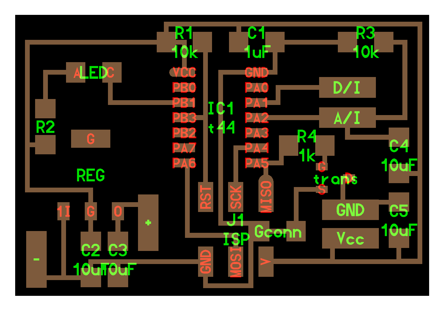
Battery is 9v so I am using the regulator to change and settle the voltage at 5v. The sensor has two outputs, one digital and one analog. The digital output gives 1 if the ppm reading is very high and close to the threshold. Analog output varies and depends on the ppm readings. The digital pin is connected to PA2 and the analog pin is connected to PA3 which has ADC. LED is connected to PB1.
The following pictures are the real size of the traces and the cut.
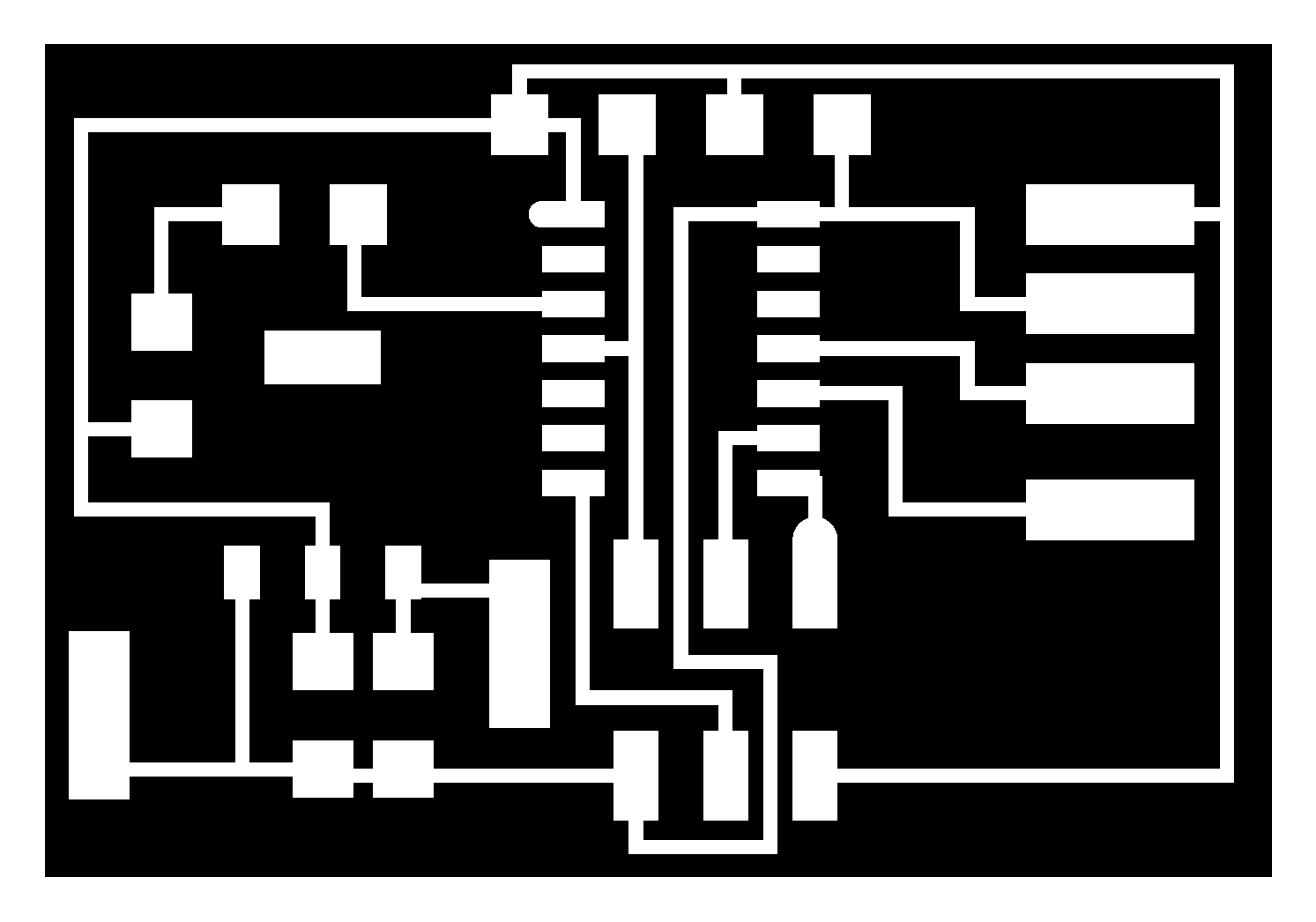

source code of the pcb can be found here.
The following is just for testing the sensor, it will be slightly modified for real uses.
/*
This program was created by Ahmad Fares on Dec-2017.
The purpose of this program is to read CO sensor values.
MIT License
*/

#define F_CPU 1000000UL
#define setbit(register, bit)   (register) |= (1 << (bit))
#define clearbit(register, bit)   (register) &= ~(1 << (bit))
#define testbit(register, bit)   (register) & (1 << (bit))

#include <avr/interrupt.h>
#include <avr/io.h>
#include <util/delay.h>


int main (void){

  setbit(DDRB, PB1); // set PB1 as output in DDRB.
  clearbit(DDRA, PA2); // set PA2 as input in DDRB.

sei();  // activate interrupts globally


setbit(DDRA, PA3);


CLKPR = (1 << CLKPCE);
CLKPR = (0 << CLKPS3) | (0 << CLKPS2) | (0 << CLKPS1) | (0 << CLKPS0);


//
// init A/D
//
ADMUX = (0 << REFS1) | (0 << REFS0) // Vcc ref
   | (0 << ADLAR) // right adjust
 | (0 << MUX5)| (0 << MUX4)  | (0 << MUX3) | (0 << MUX2) | (1 << MUX1) | (1 << MUX0); // ADC3
ADCSRA = (1 << ADEN) // enable
   | (1 << ADPS2) | (0 << ADPS1) | (0 << ADPS0); // prescaler /128

while (1) {

   ADCSRA |= (1 << ADSC);

if (ADC < 9){ // 9 is just a value for testing


clearbit(PORTB,PB1);

}else{

setbit(PORTB,PB1);
 _delay_ms(500);
clearbit(PORTB,PB1);
_delay_ms(500);

}
}
}I have had a major issue with the design. The parts could not be fitted inside the body also the switch is very big ! so I have moved on to iteration 2.

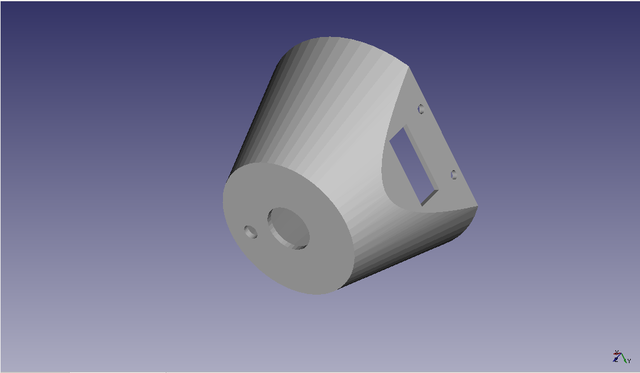
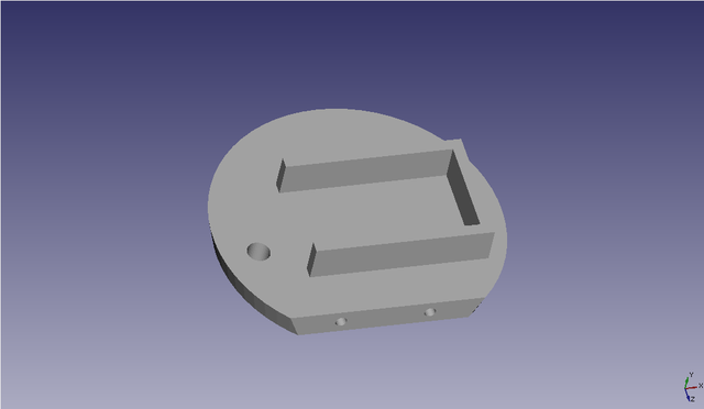
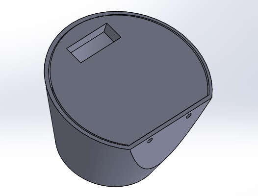
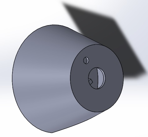
In this iteration, I have not made a major change in the design. I have increased the size, changed the place of the switch and made a place for the battery also I have designed the top cover and decided to use 3 screws to fix the cover with the body.
At the beginning, I thought that the sensor works on 5v, but I discovered that the sensor works in two cycles, heating and measuring. Heating phase requires Vcc to be 5v and lasts for 60 seconds, the purpose of this phase is to clean the sensor from any absorbed gases. Measuring phase requires Vcc to be 1.4v and lasts for 90 seconds. 1.4v is achieved by using pulse-width modulation. During measuring phase the sensor absorbs CO and gives meaningful data.
In the first time I tried the sensor, it gave me wrong measurements, I looked up in the data sheet and figured out that the sensor needs to be calibrated. There are two different ways of calibration, Rough calibration and precise calibration. Rough calibration is very easy and simple, just run the heating and measuring cycles in a clean environment for at least 10 hours, but this way will not give precise measurement. Precise calibration requires another calibrated CO sensor, flue gas, syringe and jar. I chose rough calibration so I won't go through the details of the precise calibration.
The are two changes in the design, the place of the battery is flipped so that the battery will be inside the body and the power switch has been changed from the body to the cover to allow a space inside the body for the battery
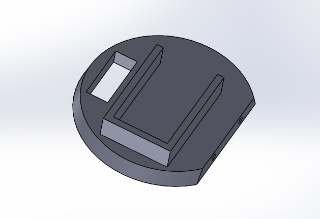
The final design looks like


Source code of the design can be found here
/*
This code was created by Ahmad Fares on 10-Dec-2017
The purpose of this is program is to read a CO sensor analog signal
and make an action.
MIT License
*/
#define setbit(register, bit)   (register) |= (1 << (bit))
#define clearbit(register, bit)   (register) &= ~(1 << (bit))
#define testbit(register, bit)   (register) & (1 << (bit))
#define togglebit(register,bit)  (register) ^= (1<<bit)
#define F_CPU 1000000UL
#include <avr/io.h>
#include <util/delay.h>
#include <avr/interrupt.h>

int counter = 0;

void setADC(){ //Set up the Analog to digital converter

  ADMUX = (0 << REFS1)|(0 << REFS0)|(0 << MUX5)|(0 << MUX4)|(0 << MUX3)|(0 << MUX2)|(1 << MUX1)|(0 << MUX0); //vcc as reference, PA2
  ADCSRB &=~(1<<ADTS2)|(1<<ADTS1)|(1<<ADTS0); //Right adject ADLAR is zero, Free running mode
  ADCSRA = (1 << ADEN)|(1 << ADPS2)|(0 << ADPS1)|(0 << ADPS0); // ADC enabled, prescaler /16

}

void setTimer(){ //set up Timer0

  TCCR0A = 0;
  TCCR0B = 0;
  OCR0A = 61;
  setbit(TCCR0A, WGM01); //CTC
  sei();
  setbit(TIMSK0,OCIE0A); // enable CTC interrupt when TCNT0 = OCR0A
  setbit(TCCR0B,CS01);
  setbit(TCCR0B,CS00); //These 2 registers set prescalar to 1/64 and start the counter.
}

void measure(){
  //Set up PWM.
  TCCR1A = 0;
  TCCR1B = 0;
  setADC();
  DDRA |= (1<<PA5);
  clearbit(PORTA,PA5);
  TCCR1A |= (1<<WGM11) | (1<<WGM10) | (1<<COM1A1) | (1<<COM1B1); //fast PWM non-inverting mode.
  TCCR1B |= (1<<WGM12)|(1<<CS10); //No prescalar.
  OCR1B = 65550 - 18350; // 1.4v
  ADCSRA =   ADCSRA |= (1 << ADSC); // Start the ADC

  //ADC value is based on the rough calibration, measurements may not be 100% accurate.
  if(ADC <= 75){ // 75 is the equivelant of 0.34v which the sensor analog output at clean environment.

     setbit(PORTB,PB1); // LED is ON.
  }else{

    clearbit(PORTB,PB1);

  }


}

void heating(){

  TCCR1A = 0;
  TCCR1B = 0; // No PWM
  clearbit(DDRA,PA5);
  setbit(PORTA,PA5); //Write 5v

}

ISR(TIM0_COMPA_vect){

  counter++;
  //2560 will allow the heating for 60 seconds.
  //2560 is calculated by experiment.
  if(counter <= 2560){

  heating();

}else if(counter > 2560 && counter <= 6400){
   //6400 - 2560 = 3840 which is equivalent to 90 seconds.
   measure();

}else if(counter == 6401){
  counter = 0;
}

}

int main (void) {

  counter = 0;
  setbit(DDRA, PA5); //PA5 output, PWM Pin
  clearbit(DDRA, PA2); //PA2 input, ADC Pin
  setbit(DDRB,PB1); // PB1 output, LED Pin
  clearbit(PORTB,PB1);
  setTimer();

while(1) {

}
}I have used PWM in Arduino, it was just one line of code but here I have to use timers and set up registers and prescalars. I spent hours trying to get the 1.4v using the PWM. At last I figured out that I must define the prescalar even if I don't want to use it.
The sensor was not working because of bad soldering.

Before I bought the sensor, I thought that it ready to use and just need power. I never thought about calibration which takes time and requires some tools. From this problem, I learned that I have to read and study anything before buying and using it.